Providing Value Driven Solutions
For Your Engineering Projects
White Shield provides value-driven solutions to a variety of engineering and construction projects in the natural and built environment throughout the Pacific Northwest
Engineering Services
Our services include, but not limited to the following:
Geographic Information Systems
White Shield provides GIS services to assist our client's understanding of our environment and to foster better decision-making. We utilize ESRI GIS systems for planning, monitoring, and mapping to maximize the efficiency of scarce resources and understanding and knowledge of our natural and built environment.

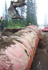
Environmental Engineering
White Shield provides a wide variety of environmental engineering services to assist our clients in complying with the myriad of local, state, and federal regulations, as well as assisting with their environmental and natural resource issues. We believe that these issues can be managed in a cost-effective and timely manner to the complete satisfaction of all stakeholders.
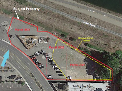
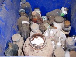
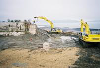
Environmental Due Diligence
White Shield provides environmental due diligence services to assist our client’s understanding and to address potential environmental liabilities associated with individual properties. Our environmental due diligence services include Phase I Environmental Site Assessments (Phase I ESA), investigations for potential contamination (Phase II ESA), remediation of identified contamination (Phase III ESA), and hazardous material inventory and waste removal.

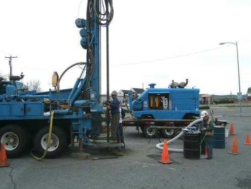
Geotechnical Engineering

What’s new in our world?
Read the latest news from WhiteShield Inc. below:
ENVIRONMENTAL DUE DILIGENCE IN REAL ESTATE: HIRING AN ENVIRONMENTAL PROFESSIONAL
Consultation with White Shield environmental professionals is recommended before closing on a real estate transaction. Today, it is customary to perform due diligence by conducting a Phase I Environmental Site Assessment (ESA) for commercial and industrial properties....

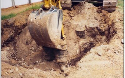
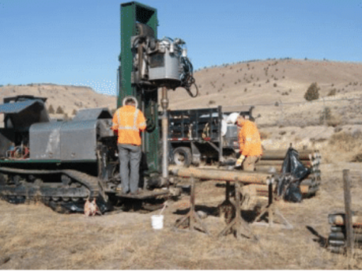
SOLUTION FOR MEASURING STRENGTH IN COARSER SOILS
White Shield geotechnical engineers provide consultation during the construction phase of projects. During construction, we observe the suitability and condition of subgrade for the placement of foundations and pavements. The subgrade or base must have suitable...
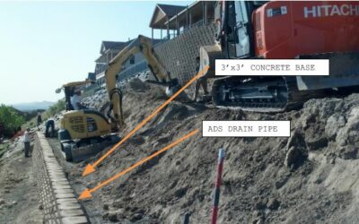
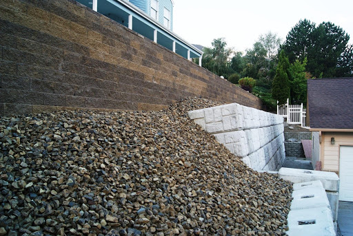
DESIGN AND CONSTRUCTION OF A TALL RETAINING WALL
Our engineers performed design and construction services for a segmental retaining wall with a finished height of 23 feet. The retaining wall was for a house located at 1348 White Bluffs Street, Richland, WA. The wall was constructed on a slope with a large amount of...
Happy Cutomers Are Talking…
We aim to please all of our clients with on time delivery and excellent solutions with traditional values! See what some of our customers are saying below:
Our Portfolio of Engineering Projects
The White Shield Team
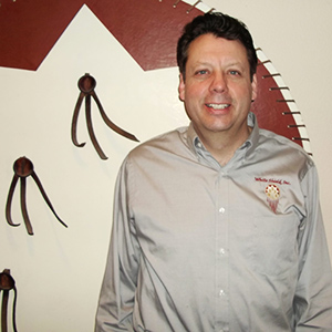
Stuart Fricke
Owner - President
Environmental and GIS Analysis
Michael Black
Principal Engineer
Civil and Geotechnical Engineer
Ron Schalla, LEG, LG, LHG
Environmental Project Manger

Bill Rodgers, LG, LHG
Environmental Project Manager