PHASE 1
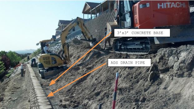
Since the existing slope did not allow adequate room for the cutback to install the correct length of geotextile, we instead opted to pour a 3-foot by 3-foot concrete block directly behind the bottom six courses of block. These blocks were placed on a compacted gravel foundation as per segmental retaining wall construction guidelines. This concrete block provided a large gravity wall section to resist sliding. The concrete was allowed to cure before any additional construction being conducted. Following the concrete placement, ADS perforated drain pipe was placed on top of the concrete and daylight drains installed at 40-foot centers. The concrete base and drainpipe can be seen in the following picture:
PHASE 2
Reclaimed asphalt pavement (RAP) with all asphalt removed was used as drainage rock behind the wall face. With the asphalt removed, this material was essentially a 5/8″ minus crushed gravel, as specified in the engineering plans. The crushed gravel was placed at the back of the wall to a minimum thickness of 12 inches. Geotextile reinforcement was then placed on each subsequent block for the next 3 rows. The grid in this phase extended 13.5 feet back from the face of the wall. All grid was laid flat with a minimum of 18 inches of overlap between panels. Grid was placed on leveled compacted fill soils from on-site with subsequent lifts being compacted before the placement of the new layer. This can be seen in the picture on the following page.

Following the three geotextile layers being placed immediately above the concrete base, the grid was placed every 2 feet of vertical wall thereafter with soil fill being compacted in 12-inch loose lifts. The geogrid was placed 13.5 feet lengths behind the wall face until the wall elevation reached the base of the existing wall.
PHASE 3
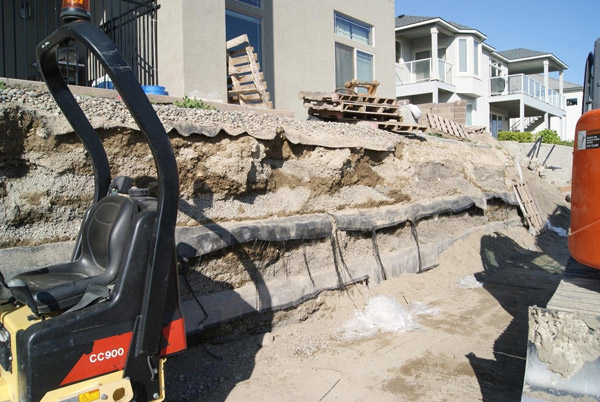
During disassembly of the existing 10-foot wall, the geofabric which had been installed to reinforce the soil mass behind it was left in place. The geotextile placed in the new wall was installed at 20-foot lengths when the elevation of the wall reached the base of the existing reinforced soil mass. This allowed us to gain strength from tying the new reinforced soil mass to the existing reinforced soil mass. The existing geofabric can be seen in the following picture:

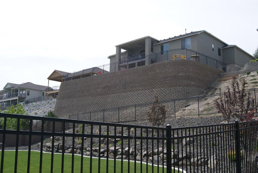
Wall construction continued in 12-inch lifts with geogrid installed every 24 inches until the elevation reached that of the existing yard elevation. We were on-site for all construction until the wall had reached a total height of 18 feet above the compacted gravel base. At that point, we made regular and customary site visits to confirm conformance with wall design plans and specifications. The completed wall with the fence installed on top can be seen in the image on the following page.

CONCLUSION
Being on-site for the majority of the wall construction, we witnessed the construction practices for the subject wall. We worked with the contractor at every step of development and ensured conformance with our design, as well as proper construction practices for segmental retaining walls. Based on the above information, we declared that the wall was installed and constructed in conformance with our design.
A note regarding compaction testing:
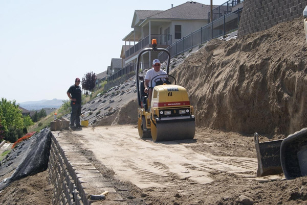
We performed testing on the soils to develop a compaction method that would allow for optimal stabilization of the fill behind the wall. A Humboldt model H-4140 soil stiffness gauge, as well as a Geostore Model S-214 portable static cone penetrometer, was used to determine the strength of the soils after compaction. As opposed to a percentage of maximum dry density, the soil stiffness gauge measures the actual engineering strength of the soils in kip/in. As the site soils consisted mainly of silt and lean clay, it is advantageous to use the soil stiffness gauge since the soils are difficult to compact. Setting a percentage (for example, 92% of maximum dry density) is problematic as the site soils may never reach 92% compaction and can actually lose strength if overly compacted. The use of the soil stiffness gauge allowed us to determine how many passes with the pictured roller would yield maximum soil strength. Periodic sampling was done in subsequent lifts to verify the compaction method. All soil stiffness measurements exceeded 35 kip/in, which is sufficient to maintain the stability of the wall and reinforced soil behind it.

